The Power Module receives power from the topside and converts it to power levels required by the various modules, sensors and accessories.
8 Pin Male Tether Connector
| Pin | Function |
|---|---|
| 1 | Interlock (GND) |
| 2 | Interlock (Sense) |
| 3 | Tether V+ |
| 4 | M100 EOP+ |
| 5 | Tether V- |
| 6 | M100 EOP- |
| 7 | RS-485 A |
| 8 | RS 485 B |
5 Pin Female High Power (Thruster, Lights) Connector (2)
| Pin | Function | Wire AWG | Color |
|---|---|---|---|
| 1 | 48 V DC + | 20 | Red |
| 2 | GND | 22 | Green |
| 3 | 48 V DC – | 20 | Black |
| 4 | RS-485 A | 24 | Gray |
| 5 | RS-485 B | 24 | White |
Power is rated at 750 Watts per port for 1,500 Watts total.
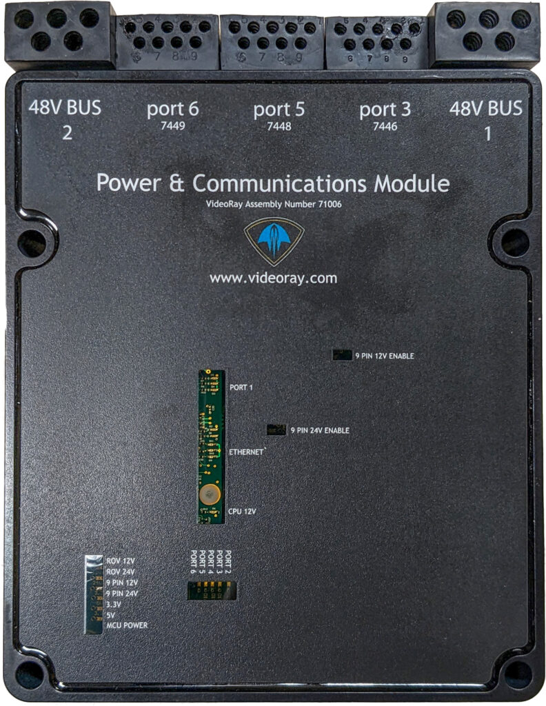
Power Module Arrangement
The communications module is the “brains” of the vehicle and coordinates vehicle control systems and provides data paths for sensors and accessories.
9 Pin Female Interface Connectors
![]() The ports are not numbered in sequence.
The ports are not numbered in sequence.
| Pin | Function |
|---|---|
| 1 | ETH_RXP + |
| 2 | ETH_RXP – |
| 3 | 24 V DC + |
| 4 | ETH_TXP + |
| 5 | GND |
| 6 | ETH_TXP – |
| 7 | RS-485 A |
| 8 | RS-485 B |
| 9 | 12 V DC + |
Power is rated at 300 Watts for the 24 Volt circuit and 120 Watts for the 12 Volt circuit. This is the total output of the internal DC/DC converters and is divided across all connections as demanded by each externally connected device. Each connector pin is rated to 5 Amps, which should not be exceeded. For any one connector, the maximum Watts should not exceed 120 Watts for the 24 Volt circuit and 60 Watts for the 12 Volt circuit.
Communications Module Arrangement
| Port Number | Module/Device Assignment | TCP Port | Baud Rate | Notes |
|---|---|---|---|---|
| 1 | Power | 7444 (vrport1) | 115200 | |
| N/A | Communications Module | 7444 (vrport1) | 115200 | |
| 2 | N/A | N/A | ||
| 3 | High Definition Camera | 7446 | ||
| 4 | N/A | N/A | ||
| 5 | AHRSD | 7448 | ||
| 6 | Rotating Manipulator | 7449 | 115200 (Reach Alpha Manipulator Only) |
Defaults: Group ID – 193; Node ID – 2; IP address – 192.168.1.64; RS-485 accessible