The Mission Specialist ROV system uses 3 types of connectors for power and communications between the control panel, vehicle modules and accessories.
8 Pin Tether Connector
 | 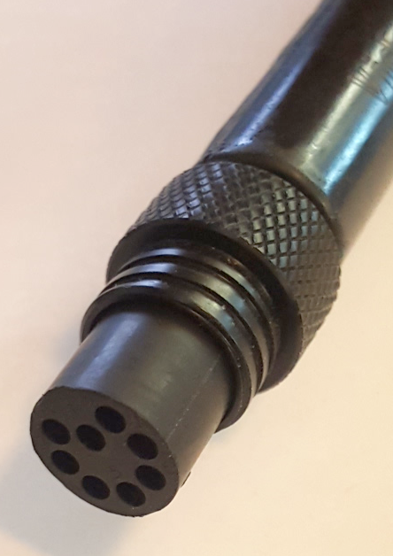 | Pin Function 1 Interlock (GND) 2 Interlock (Sense) 3 Tether V+ 4 M100 EOP+ 5 Tether V- 6 M100 EOP- 7 RS-485 A 8 RS 485 B |
Pin numbering starts at 1 for the offset pin and is clockwise on the male connector and counter clockwise on the female connector.
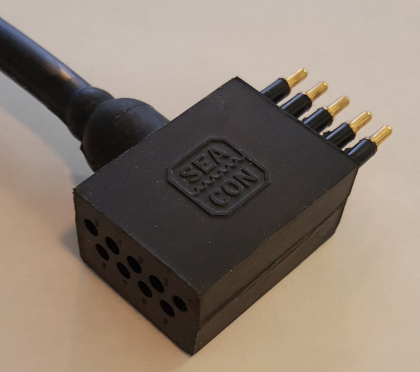
5 Pin Thrusters and Lights Connector
 | Pin Function 1 48 V DC + 2 Vehicle Local Ground (12 V, 48 V return) 3 48 V DC return 4 RS-485 A 5 RS-485 B |
Pin numbering is clockwise starting at 1 in the upper left when looking at the face of the male connector with the row of 3 pins on top.
9 Pin Accessory Connector
 | Pin Function 1 ETH_RXP+ 2 ETH_RXP- 3 24 V DC + 4 ETH_TXP + 5 Ground 6 ETH_TXP – 7 RS-485 A 8 RS-485 B 9 12 V DC + |
Pin numbering is clockwise starting at 1 in the upper left when looking at the face of the male connector with the row of 5 pins on top.